



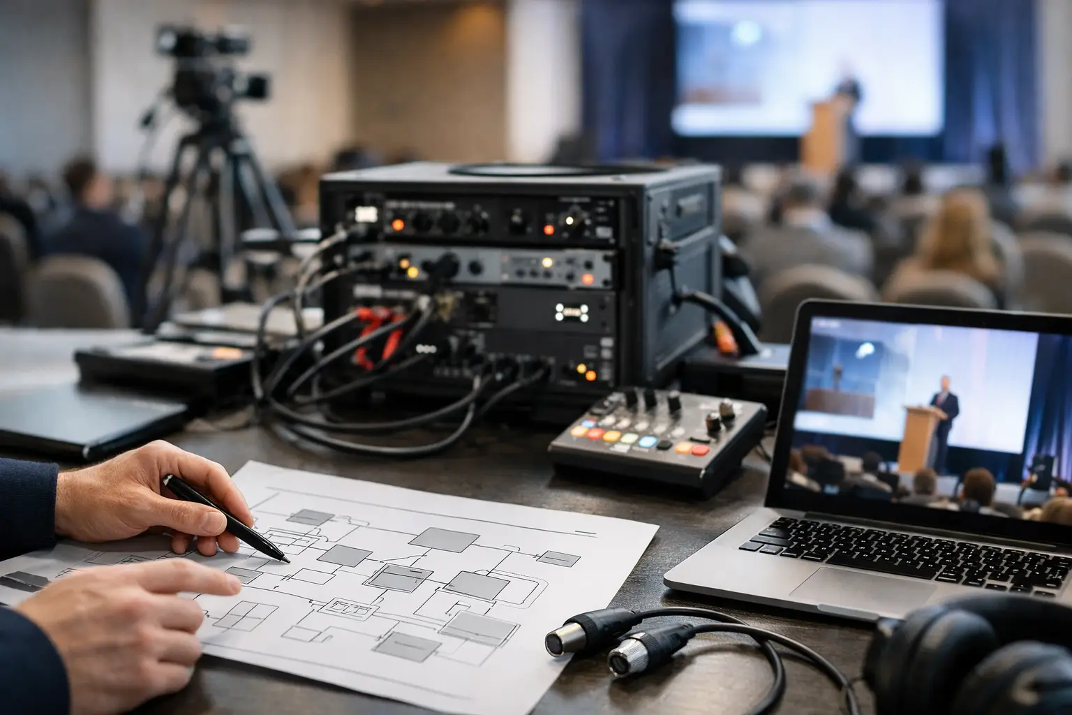
How to Plan Conference Signal Flow Without Gaps
A conference can look completely rehearsed until one signal goes somewhere it was never supposed to go.
The CEO walks onstage and the confidence monitor is black. The ballroom sees the correct presentation while the livestream receives the backup laptop. Playback audio reaches the room but never reaches the stream.
Those failures rarely begin when the cue is called. They usually begin during preproduction, when nobody clearly defined how to plan conference signal flow from every source to every destination.
For corporate conferences, signal flow is more than an engineering diagram. It is the operating plan that explains where every video and audio source originates, where it is processed, which destinations receive it, who owns each handoff, and what happens when a critical path fails.
How to Plan Conference Signal Flow: Start With the Destinations
One of the easiest mistakes is beginning with the equipment list:
- Cameras
- Presentation laptops
- Playback computers
- Video switchers
- LED processors
- Encoders
Those devices matter, but they do not define the production.
The destinations do.
Start by listing every place that needs to receive video, audio, data, or control.
A corporate general session may include:
- Main LED wall
- Left and right side screens
- Downstage confidence monitors
- Speaker timer
- Teleprompter
- Lobby overflow displays
- Press feed
- IMAG program
- Livestream program
- Recording
- Remote presenter return
Those destinations do not necessarily receive the same thing.
The ballroom may see slides and IMAG.
The presenter may see slides, notes, and a timer.
The livestream may receive cameras, slides, lower thirds, captions, and a completely different layout.
Understanding those differences is the foundation of the signal-flow plan.
Create a Source and Destination Matrix
Before drawing cables, create a simple matrix showing what every source needs to feed.
For example:
| Source | Main LED | Confidence | IMAG | Livestream | Record |
|---|---|---|---|---|---|
| Main Deck | Yes | Yes | As needed | Yes | Yes |
| Camera 1 | IMAG | No | Yes | Yes | ISO |
| Playback A | Yes | Optional | Yes | Yes | Yes |
| Remote Guest | Yes | Optional | Yes | Yes | Yes |
The matrix does not replace the full diagram.
It makes the diagram easier to build because the production team already understands the routing requirements.
Inventory Every Source Before Designing the System
Once the outputs are understood, document every source that can enter the system.
Common sources include:
- Main presentation laptop
- Backup presentation laptop
- Playback A
- Playback B
- Graphics
- Camera feeds
- Remote contributors
- Product demo computers
- Walk-in content
- Lobby or sponsor content
Do not assume every source behaves the same way.
A PowerPoint laptop may be 1920×1080.
A wide LED playback system may be outputting a custom raster.
A product demo computer may unexpectedly switch refresh rate.
A remote caller may arrive at a completely different frame rate.
The signal-flow design should normalize those differences before they reach critical displays or recording paths.
Separate Presentation, Playback, Camera, and Graphics Paths
I prefer keeping these source families clearly separated before they meet inside the larger production system.
Presentation
Presentation computers typically feed the screen-management system and may also be captured for livestreaming and recording.
Playback
Playback systems may provide standard 16:9 video, wide LED content, lower thirds, stingers, or other media.
Our guide to corporate event video playback covers Millumin, Mitti, ProVideoPlayer, PIXERA, wide canvases, 16:9 playback, and backup playback workflows.
Cameras
Cameras generally feed a production switcher first, where the director creates IMAG, livestream, recording, or other program outputs.
Camera positions should also be designed with the signal path in mind. Our guide to conference camera placement covers long-lens cameras, IMAG, livestream framing, PTZ systems, and audience coverage.
Graphics
Lower thirds, titles, timers, and other graphics may come from dedicated systems or playback applications depending on the production.
Keeping these paths organized makes troubleshooting much faster.
If presentation disappears from confidence monitors, the engineer can investigate that path without disturbing camera program.
Decide Where Sources Actually Meet
A conference may contain both a production switcher and a screen-management processor.
They perform different jobs.
A production switcher may handle:
- Camera cuts
- Livestream program
- Recording program
- Graphics keys
A screen-management processor may handle:
- LED canvases
- Projection screens
- Presentation layouts
- IMAG windows
- Multiple display destinations
- Confidence-monitor routing
On more complex general sessions, a Barco E2 or Encore3 may become the control point for presentation sources and screen destinations.
Barco’s Event Master platform is designed for professional screen management across multiple displays and canvases.
The important part is deciding clearly which device owns which decision.
Document Every Conversion Point
Every conversion is another place where signal behavior can change.
The signal-flow document should show where:
- HDMI becomes SDI
- SDI becomes fiber
- DisplayPort becomes HDMI
- Signals are scaled
- Frame synchronization occurs
- Audio is embedded
- Audio is de-embedded
If the production standard is 1080p59.94, verify that critical devices are operating at that standard where appropriate.
Automatic format detection is useful, but I do not like depending on it for mission-critical paths if the show can be standardized beforehand.
Separate Physical Signal Flow From Logical Signal Flow
This is especially useful on larger productions.
The physical diagram shows:
- Cables
- Converters
- Routers
- Processors
- Switchers
- Fiber paths
The logical flow explains what the signal is being used for:
- Presentation
- IMAG
- Stream
- Record
- Confidence
- Backup
One cable may carry a signal that serves several logical purposes farther downstream.
Separating those two views can make a complicated system much easier to understand.
Name Everything Consistently
Signal flow becomes harder than necessary when every department uses different names.
If the main presentation computer is:
SL-01 Main Deck
that name should ideally appear consistently on:
- Signal-flow diagram
- Processor input
- Switcher label
- Multiview
- Run of show
- Operator notes
Avoid situations where one device is called:
- Laptop 1
- Main Deck
- House PPT
- Graphics A
depending on which document someone is looking at.
Consistent naming reduces questions during the show.
Design the Screen Architecture Around What Each Surface Needs
A modern conference stage may contain multiple independent visual destinations.
For example:
- Main LED: presentation + IMAG
- Side screens: camera or presentation
- Confidence 1: current slide
- Confidence 2: next slide + timer
- Livestream: camera + slides + graphics
Do not assume every display should mirror the same output.
The technical system should reflect how each audience or operator actually uses the display.
LED Walls Need Their Own Downstream Signal Plan
When the destination is LED, the signal path continues beyond the E2 or switcher.
It may include:
- Screen-management processor
- LED processor
- Sender
- Receiving cards
- LED cabinets
Resolution, raster size, frame rate, scaling, and color behavior should remain predictable through that chain.
Our guide to corporate LED wall calibration covers cabinet uniformity, brightness, gamma, show-site tuning, camera compatibility, and full-path validation.
Treat Audio as a Parallel Signal System
Video receives a lot of attention because the screens are visible.
Audio problems can be even more damaging.
The audio system should clearly document:
- Presenter microphones
- Playback audio
- Walk-in music
- Remote-call returns
- Audience microphones
- Interpretation
- Press feeds
- Stream mix
The ballroom mix and the livestream mix do not necessarily need to be identical.
A room may naturally hear audience reaction and reinforcement from the PA.
The remote viewer needs those elements intentionally mixed into the broadcast feed.
Define Embedded-Audio Handoffs
If playback or presentation audio arrives embedded in SDI or HDMI, define exactly where it enters the audio system.
For example:
Playback computer → E2 input → de-embed → audio console
or:
Playback computer → audio interface → audio console
Either approach can work.
What matters is that both departments understand the handoff.
Hybrid Events Add Another Complete Signal Path
A hybrid event effectively creates another audience.
The online audience may require:
- Camera program
- Presentation capture
- Lower thirds
- Captions
- Dedicated audio mix
- Remote guest return
- Mix-minus
The outbound path may look like:
Switcher → encoder → internet → platform → viewer
But that is only one direction.
A remote presenter also requires a return path.
Map both directions.
Monitor the Stream After the Encoder
One common signal-flow gap is monitoring only the local production system.
The switcher multiview may look perfect while the streaming platform is receiving nothing.
The production position should ideally be able to monitor:
- Local program
- Encoder output
- Platform ingest status
- Actual viewer return
That last monitor is important because it represents what the audience actually receives.
Internet Is Part of Signal Flow
For livestreaming, the signal path does not stop at the encoder.
The network becomes part of the AV system.
Plan:
- Primary internet
- Backup internet
- Router or bonding system
- Encoder connection
- Platform destination
Our guide to livestream internet failover setup explains independent WAN paths, traditional failover, bonding, cellular backup, monitoring, and forced-failure testing.
Design Redundancy Around Consequence
Not every signal needs a duplicate path.
Redundancy should protect the failures that would seriously affect the program.
That may include:
- Main presentation
- Critical playback
- Main screen processing
- Program output
- Livestream encoder
- Internet connectivity
- Recording
The backup should be operationally simple.
If changing to the backup requires ten minutes of repatching and configuration, it is not an effective live-show recovery path.
Draw the Backup Paths on the Diagram
Do not document only the happy path.
Show:
- Main Deck → Primary Input
- Backup Deck → Backup Input
- Playback A → Primary
- Playback B → Backup
- Primary encoder → Main stream
- Backup encoder → Alternate path
A backup that exists only in someone’s memory is much harder to use under pressure.
Assign Ownership at Every Handoff
A signal-flow diagram tells you where the signal goes.
It should also be clear who owns the relevant handoff.
For example:
- Presentation operator owns deck output
- Playback operator owns playback content
- E2 operator owns screen destinations
- TD owns video program
- A1 owns audio routing
- Streaming engineer owns encoder and platform path
Titles vary between productions, so the exact roles matter more than the labels.
Connect Signal Flow to the Run of Show
A static routing diagram does not explain when the routing changes.
That is where the run of show becomes important.
A destination might display:
- Walk-in loop before the show
- Presentation during keynote
- IMAG during panel discussion
- Playback during product reveal
The signal-flow plan explains what is possible.
The event run of show explains when each state happens.
Turn the Signal Diagram Into a Full Show Package
For a complex conference, the signal-flow diagram works best alongside:
- Source list
- Destination list
- Input list
- Output list
- Patch list
- Cable schedule
- IP plan
- Power plan
- Stage plot
- Camera plot
- Run of show
All of those documents should use consistent naming.
Test the Entire Path During Line Check
Do not test only whether the source appears at the first processor.
Verify the actual destination.
For presentation:
Laptop → processor → LED → confidence monitor → stream → recording
For cameras:
Camera → switcher → IMAG → stream → record
For playback:
Playback → processor/switcher → room → audio → stream → record
That is a real end-to-end test.
Then Break the System on Purpose
A good technical rehearsal should test more than normal operation.
Try:
- Disconnecting the main presentation computer
- Taking the backup playback path
- Dropping a remote contributor
- Switching internet connections
- Testing a backup processor input
The crew should know what the audience sees while recovery is happening.
A useful backup system gives the operator somewhere safe to go.
Conference Signal Flow Checklist
- All destinations listed
- All sources listed
- Source/destination matrix created
- Presentation path documented
- Playback path documented
- Camera path documented
- Graphics path documented
- Audio handoffs documented
- Remote guest paths documented
- Stream path documented
- Recording path documented
- Format conversions identified
- Frame-rate standards confirmed
- Scaling points identified
- Embedded audio identified
- Device naming standardized
- Backup paths shown
- Critical handoffs assigned to an owner
- Primary paths tested end to end
- Backup paths tested end to end
- Signal flow matched to the run of show
- Full failure tests completed during rehearsal
The Best Signal Flow Is Quiet During the Show
A well-designed signal-flow system should almost disappear once the show starts.
The audience should not know how many routes, converters, processors, backup sources, monitors, and recovery paths are working behind the scenes.
They should simply see the correct content, hear the correct message, and remain focused on the conference.
That is ultimately how to plan conference signal flow: understand every destination, define every source, control every handoff, and build a clear recovery path for the parts of the show that cannot fail.
Need Help Planning Conference Video and Signal Flow?
AV Land provides technical direction, Barco E2 and Encore3 operation, camera production, playback, LED video systems, livestreaming, recording, and conference production support throughout the San Francisco Bay Area and beyond.
Contact AV Land to discuss your next conference or corporate event.
Conference Signal Flow FAQ
What is conference signal flow?
Conference signal flow describes how audio and video travel from sources such as cameras, presentation computers, playback systems, and remote presenters through switchers, processors, routers, encoders, and other devices before reaching displays, speakers, livestreams, recordings, and other destinations.
Should signal flow start with sources or outputs?
For planning purposes, it is often useful to define the required destinations first so the production team understands what each audience and display needs. The system can then be designed from the sources forward to satisfy those requirements.
What should be included on a signal-flow diagram?
A useful diagram should identify sources, processors, switchers, conversions, routers, major transport paths, outputs, important format changes, and backup routes. Complex productions may also maintain separate network, audio, power, and patch documentation.
Why should playback and presentations use separate paths?
They have different operational roles and failure modes. Keeping them clearly organized makes troubleshooting easier and allows one path to be changed without unnecessarily affecting another.
Should livestreaming be part of the signal-flow diagram?
Yes. The flow should continue beyond the encoder to include the production network, internet path, streaming platform, and audience monitoring where appropriate.
Do E2 and Encore3 replace a production switcher?
Not necessarily. Screen-management processors and production switchers often perform different roles. A switcher may primarily manage camera program and broadcast-style switching, while E2 or Encore3 manages multi-screen destinations, presentation layouts, scaling, and screen composition.
How should backup signal paths be documented?
Draw them on the same diagram or a clearly associated backup diagram and identify how operators activate them. A backup should be connected, configured, labeled, and tested before show time.